2 Software Overview
On startup the Welcome dialog is shown with shortcuts to open recently opened project files and the Capture news feed. Once this has been closed, the main Capture interface remains.
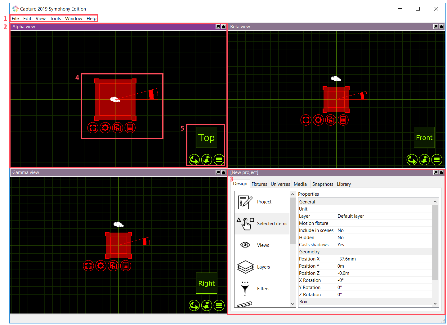
The main components of the interface highlighted in the image are:
- Main menu.
- Design views (three in total).
- Project window.
- Navigator selection interface.
- Navigator view interface.
2.1 Main Menu
The main menu is available at the top of the main window.
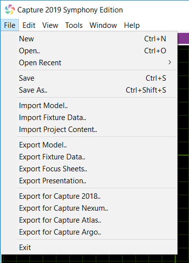
In the File menu you will find the basic commands for opening, saving and closing Capture project files. Note the variety of different options are available for opening older Capture project files.
The Import Model feature is used to open up other project files in parallel and allows you to copy items from other projects into the project you are working with (which is done using the arrow navigator button).
The Import Data feature allows you to import a variety of drawing formats from other programs, as well as specific project data such as fixture patch, weight, etc.
The Import Project Content feature allows you to import layers, filters, reports, plot styles and plots from another project.
The Export Presentation feature that allows you to create an executable file that will launch your project, which is embedded in the executable file, and show the Alpha view. Presentations cannot be used to edit project files, they merely serve as a viewing and presentation tool.
The Export for Capture Nexum, Atlas, Argo functions allow you to export your project to older versions of Capture.
The Export focus sheets feature creates a set of images, one per fixture (or as configured in the configuration dialog presented), giving you a view out through the aperture of the fixture. It requires you to pick a folder into which the images are placed.
In the Edit menu you will find access to the unlimited Undo and Redo commands.
The Tools menu gives you access to the Options window and the Translation window.
2.2 Design Views
Capture has three design views, Alpha, Beta and Gamma. These views can be configured to the users liking. Configuring a design view is done by clicking on the green list button as shown below.
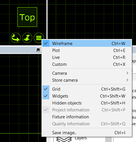
| Command | Description |
|---|---|
| Wireframe | Wireframe is the default view and works as a 3D CAD wireframe view whereby a user can orbit any object in 3D but it is only rendered in wireframe. |
| Plot | Replaces the Paper view from previous Capture versions. This view is used to make plots. |
| Live | Live 3D rendering view. |
| Custom | In Custom mode, you can configure your own look view with either wireframe/solid, perspective/orthographic etc. |
| Camera | Camera shows a list of preset camera positions for quick navigation, as well as the ability to launch one of the user made camera positions. |
| Store Camera | By positioning the camera to a user defined location, a user can then go to the Store camera option and choose a camera preset to store the current camera pose to. |
| Grid | Grid toggles the grid on/off for the selected view. |
| Widgets | Widgets (such as the camera) can be toggled on/off for the selected view. |
| Hidden Objects | Hidden objects can be toggled on/off for the selected view. |
| Project Information | Toggles the project information on/off for the selected view. |
| Fixture Information | Fixture information replaces the previous Live Information option from Capture Argo. It overlays fixtures with programming information like shutter and color mix status. |
| Quality Information | Toggles the FPS and quality info on/off for the selected view. |
| Save Image.. | Save an image of the currently selected view. |
Some view settings are not available in the navigator. Additional settings for each view are available in the Design tab of the Project window. With the Views category selected, each view has one column of properties appear on the right hand side.
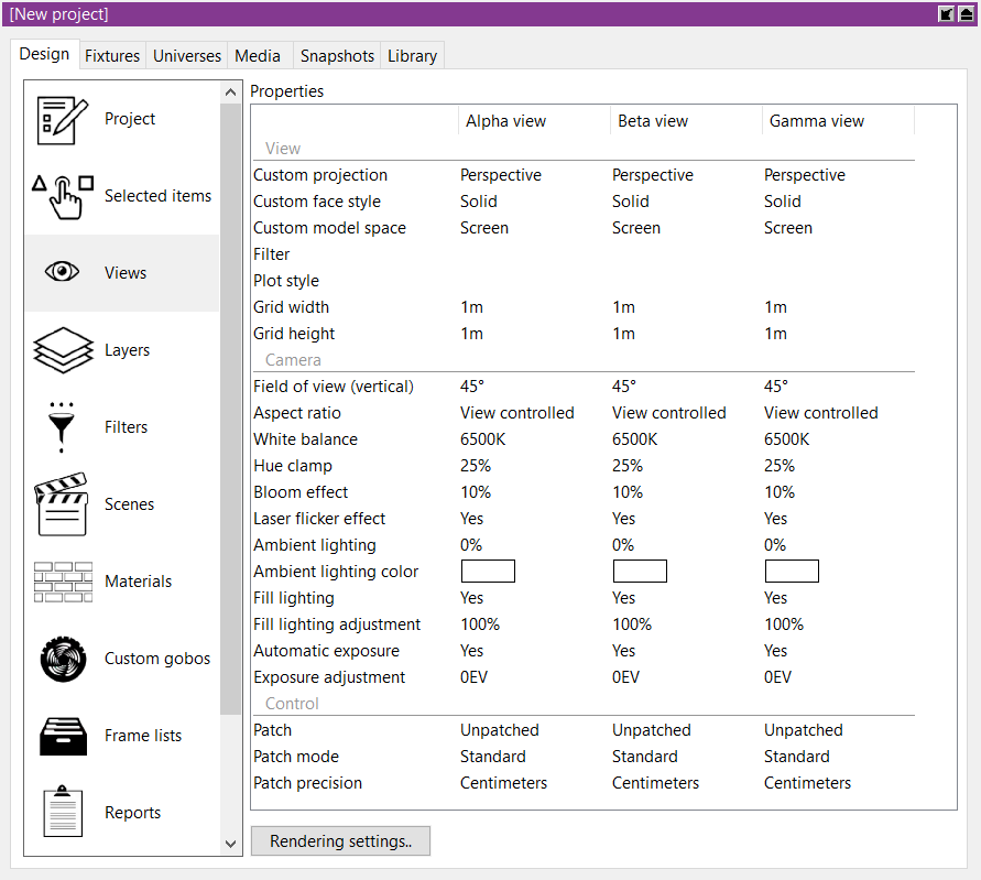
The Grid width and Grid height properties determine the distance between grid lines.
The Vertical field of view property lets you control lens angle of the view’s camera.
The Aspect ratio of a view can be set to follow 4:3 as well as 16:9.
The Brightness, Exposure and Atmosphere settings controls the look of the view when in Live mode. If you have enabled the “Simpler Graphics” option of Capture, Brightness and Exposure are replaced with Fixture Lighting and Fixture Lighting Differentiation.
2.2.1 DMX Control
It is possible to control a view using DMX. This is achieved by either manually assigning a Patch universe / channel or by dragging the view’s camera from a design view to a channel in a Universe view. The Patch mode option can be used to select the number of channels used by the camera. See Append A for details on the DMX channel layout.
2.3 Project Window
The Project Window is the main information area in Capture. It hosts the properties for the selected items, additional settings for the Alpha, Beta and Gamma Views, settings for Layers and Filters, Scenes, Materials, Custom Gobo wheels, Custom Frame (color) lists, Reports Plot styles and Plots. Furthermore, the window is split into a navigation list down the side with the properties for whatever is selected from that list available on the right. Along the top are some tabs - Design, Fixtures, Universes, Media, Snapshots and Library. Generally speaking, to add an object of any type to a capture project, it needs to be dragged from the library tab to one of the design views. Objects can only currently be dragged into a wireframe or plot view.
2.4 Navigator
The Navigator is one of the main tools of capture. It is used for two primary functions - Navigation and Manipulation.
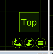
The navigation part of the Navigator is present in the bottom right corner of the Alpha, Beta and Gamma views. This Navigator is used to manipulate the view in terms of changing the camera viewing point and zoom within the view as well as accessing the view settings via the spanner button.
The First button, a curve with arrows, allows you to move around a view. Holding the Shift or Ctrl keys allows a different style of movement in the 3D views.
The second button is used to zoom in and out on the selected view. Holding the button and moving the mouse up or down will control the amount the camera is zoomed in or out.
The third button is used to access the settings for the selected view as we discussed earlier. Additional settings for each are available in the Design tab of the Project window.
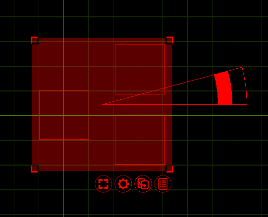
Whenever you select any objects, within any of the Alpha, Beta or Gamma views within Capture; a second type navigator appears. When objects are selected, they appear red with a a red grid around them that has some control buttons below it. This second type of navigator is used to assist in the manipulation of the objects.
Objects can be selected by clicking on them with the mouse. Use the Shift key to add objects to the selection and the Ctrl key to toggle individual object selection on and off. By click-dragging the mouse over a group of objects, you can select them all at a time. If you drag from the left to the right, the objects must lie completely within the region, but if you drag from the right to the left, it is enough for the objects to be partially inside the region in order to become selected.
Clicking and moving the mouse anywhere inside the Translation grip allows you to move objects around. This area is intentionally large so that it is easy to move items. While moving items, you can enable the ortho mode by pressing Shift key. Snapping in the sense of bringing items to a minimal distance is built in and activated during any translation, but is not triggered until after a short delay. When snapping is activate, the result of the snapping is illustrated with an alternate colour.
Clicking and moving the mouse inside a Distribution grip will allow you to spread out or bring together the selected objects over the given area in a proportional manner. The ortho mode is available here by using the Shift key as well. The Rotation anchor is used to rotate objects. It can be moved around to define the center of rotation and allows for both Individual rotation and Group rotation. Pressing the Shift key enables snapped rotation.
The first button is the selection menu button. It allows you to select or deselect everything, with the added “layer” option. Using the “layer” option will allow you to select or deselect everything but only in the current layer. Layers will be discussed in a later chapter.
The second button is the actions menu button. It displays a small list of possible operations relevant to the selected object(s). The list that appears is context sensitive, that is to say that selecting a Lighting Fixture will display different options in the list than that of a Truss. Each available option/command will be covered later in the relevant chapters.
The arrow button is used to drag objects out of one view to another. Using this button, the objects won’t actually move per say. The button is used primarily for patching fixtures. Select multiple fixtures in the order you wish to patch them and use the drag button to drag them onto a universe in the project window or on an open universe window. This functionality will be covered later in the relevant section.
You may also use the arrow button to drag the object to a new location in the same window, thereby making a copy.
The button with a list is the Quick Summery button. Pressing it when you have objects selected presents a popup window about the selected objects displaying key data about them. This button reveals the fixture control pane and is only visible when at least one lighting fixture is selected and the view is in Live mode.
2.5 Smoke Settings
Smoke is added to and managed using smoke boxes. New projects contain one auto sizing smoke box by default. The presence of a smoke boxes is indicated by a cloud widget and when selected its extents become visible. Smoke boxes can be deleted as any other object and more smoke boxes can be added from the Library tab at any time.
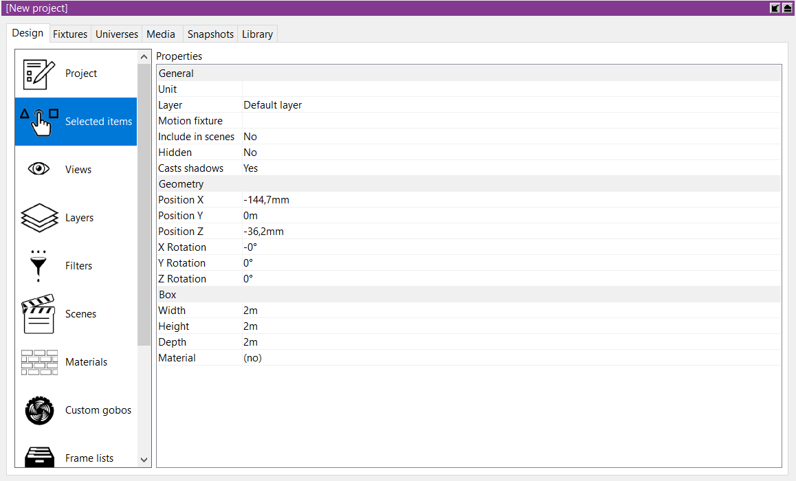
To adjust the properties of a smoke box, select it and edit its properties in the Selected Items category in the Design tab.
Control the overall amount of smoke in a smoke box using the Density property. You can also adjust the Variation from perfect haze to puffy clouds. Edge softness adds a soft edge to smoke boxes.
Smoke boxes are animated in real-time and the speed of the animation is controlled through the Speed property. This property is shared by all smoke boxes.
Typical applications of more than one smoke box include denser smoke on stage in an arena with otherwise thin haze as well as localized fog situations such as heavy fog or fog behind a glass.
Limiting smoke to the area around the stage also helps avoid problems with beams shot into the audience oversaturating the visualisation. The Smoke element is in a new project by default (much like the camera object).
Smoke can also be patched to DMX. A smoke box can be patched by drag and dropping it in a DMX universe view like any fixture, or by assigning an address to the Patch property in the Design tab. See Appendix A for details on the DMX channel layout.
2.6 Rendering Settings
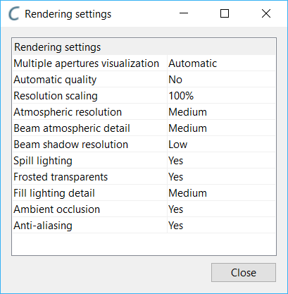
The rendering settings (previously visualization settings, under software options) is available as a button in the Views category of the Design tab. Its properties control the rendering quality of the live design views.
The Multiple Apertures visualization option controls the rendering of multi-aperture (striplights, BB-7, multi-LED moving heads) beams. In simple mode, only a single beam is rendered using the fixtures average color.In realistic mode each aperture renders a beam of its own. In Automatic mode a single beam is rendered for the fixture when all apertures have the same color.
The Beam Atmospheric Detail option allows you to control the level of detail created by a beam passing through the smoke/haze in the atmosphere.
The Beam shadow resolution option allows you to lower the resolution of shadows created by beams.
The Automatic Quality option allows you to turn on/off the automatic quality functionality Capture uses. Having automatic quality turned on will allow capture to be more efficient while rendering more complex scenes by sacrificing quality to keep good performance.
The Resolution Scaling option allows you to render live visualization at a lower resolution than the screen.
The Atmospheric Resolution option controls the resolution of atmospheric visualization, (Smoke). The Beam Atmospheric Details option allows you to control the level of detail created by a beam passing through the smoke/haze in the atmosphere. Higher levels of Beam Atmospheric Detail are relevant when using many wide angle beams and/or shooting through scenery that intersects beams.
The Beam Shadow Resolution option allows you to increase the resolution of shadows created by beams when shooting over long distances or on/through scenery.
The Spill Lighting option enables the visualization of a beam contribution beyond a fixtures field angle.
The Frosted Transparents option allows you to disable the visualization of the frosted effect of transparent materials.
2.7 Software Options
The software options are available through the Tools menu Options command and are split in two categories.
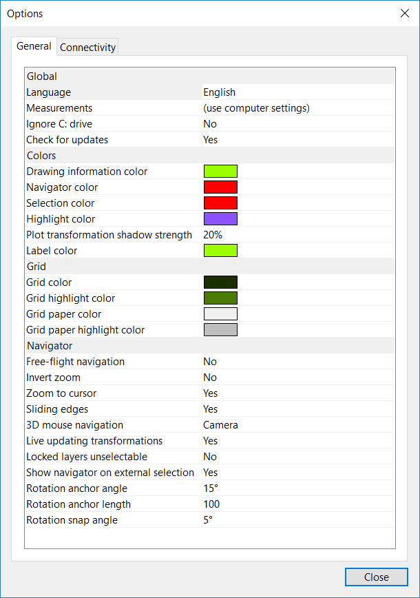
2.7.1 General Options Tab
Here you can change the language of the user interface in Capture. By default it will follow the settings of your computer.
The Ignore C: drive options is important on Microsoft Windows machines that have their Windows installation on a drive other then C :
Turning on the Live updating transformation option causes all simulation views to update at once when moving or rotating objects.
Locking layers is a useful way of preventing accidental modification of fixed items such as the house of your venue. The Locked layers unselectable option takes it one step further and prevents you from even selecting such items.
The Show navigator on external selection is a feature for users with controllers that are capable of selecting fixtures. Unless this option is enabled, fixtures selected from a controller will only highlight as red and not display the navigator with the command buttons.
Free-flight navigation is normally accessible using the Shift key when navigating but can be set as the default behaviour instead (in which case the Shift key can be used to access orbit navigation).
The size of the navigators rotation anchor can be changed with the Rotation anchor angle and Rotation anchor length options. The rotation anchor snapping angle can be set with the Rotation snap angle option.
2.7.2 Connectivity Options Tab
This tab contains options for controller and media server connectivity. It can be important to set the Preferred network address on a machine with multiple network addresses, but unless you are connecting to older equipment it is not encouraged to enable the Compatible CITP mode as it may make it impossible to connect to newer equipment.
You may also alter the incoming video format for CITP communication.
By default, Art-Net, sACN (E1.31), Compulite VC, ETC Net 2, HippoMap (HMap3), Lan Box, Lasergraph DSP and PangolinLD are all set to Automatic. On rare occasions when a machine has more than one network adapter, it may be necessary to change Automatic to a specific IP address available under the relevant protocol.