5 Fixtures
5.1 Fixtures Overview
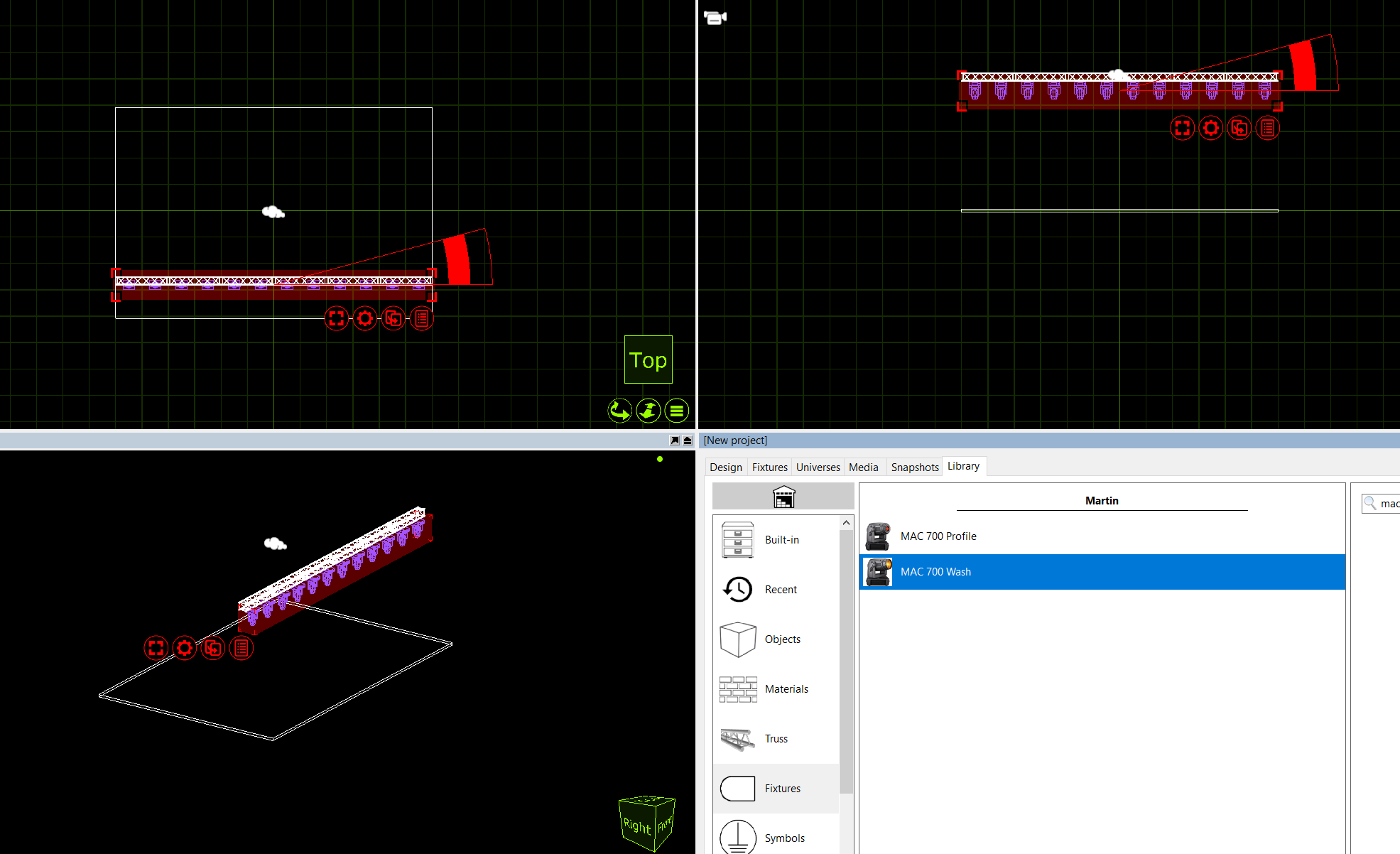
Fixtures are handled in pretty much the same was as other objects. To add a fixture, it needs to be dragged from the library to one of the wireframe design views. Fixtures can be cloned, moved, rotated and deleted the same as any other object.
In this example, we add a single Mac 700 profile from the library. We then clone it so that we end up with one Mac 700 per meter of the truss.
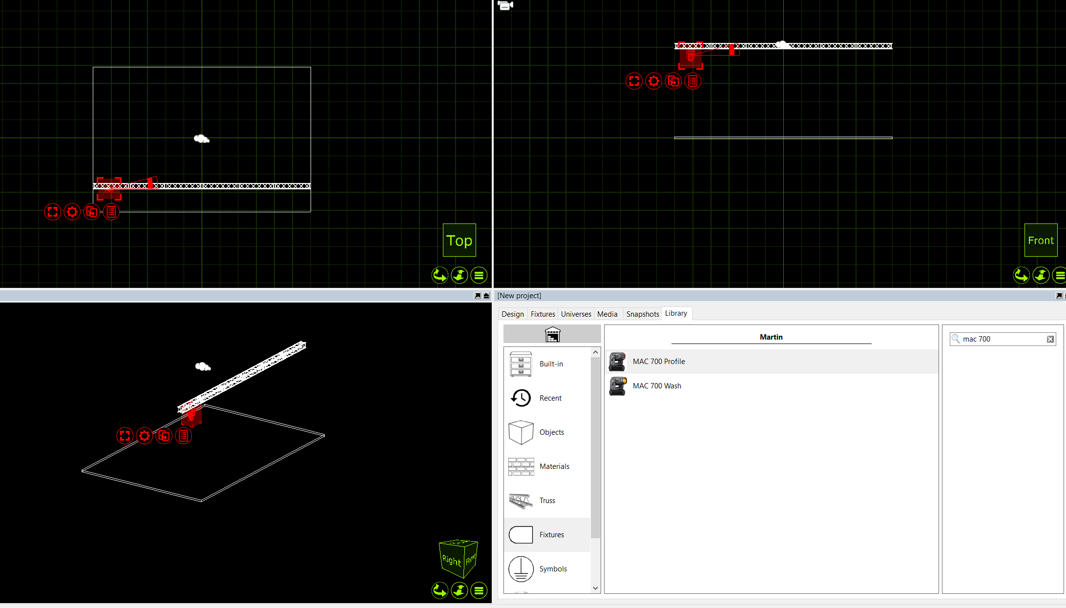
Clone the Mac 700 Profile 11 times so the 12m truss has 1 Mac 700 every meter. The Mac 700’s will then span the truss equally.
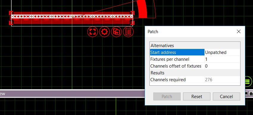
Now that we have added the Mac 700’s. They need to be patched. There are two ways of patching fixtures in Capture. You can select the fixtures you wish to patch, in the order you want them patched, and from the red spanner (options) menu, you can select “Sequential Patch”. The sequential patch window will appear giving you the options of “Start Address”, which is formatted by double clicking the option and entering Universe.Address. For examples entering 2.1 would patch the fixtures to Universe 2, Address 1.
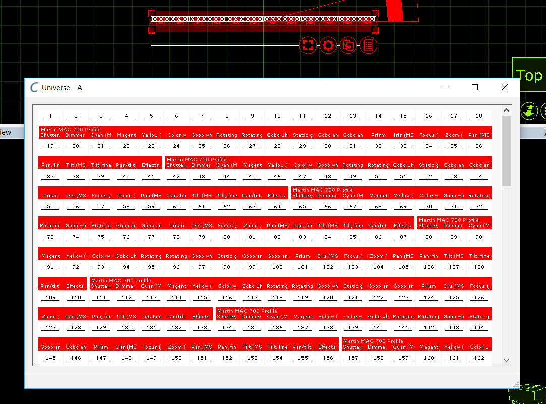
The second option is to drag the fixtures to a start address within a universe window. First, open one of the project universes by clicking on the Edit button in the Universes tab of the Project Window. Then select the fixtures in the order you wish to patch them, click and hold the drag button and drag them to a start address in the open universe window.
5.2 DMX Universes
Once fixtures are patched onto Captures internal universes, you can link those internal universes to external universes that are coming into Capture via protocols like Art-Net or sACN. Very little user intervention is required with most of these protocols - Capture will accept most of them in a “Plug & Play” kind of manner.
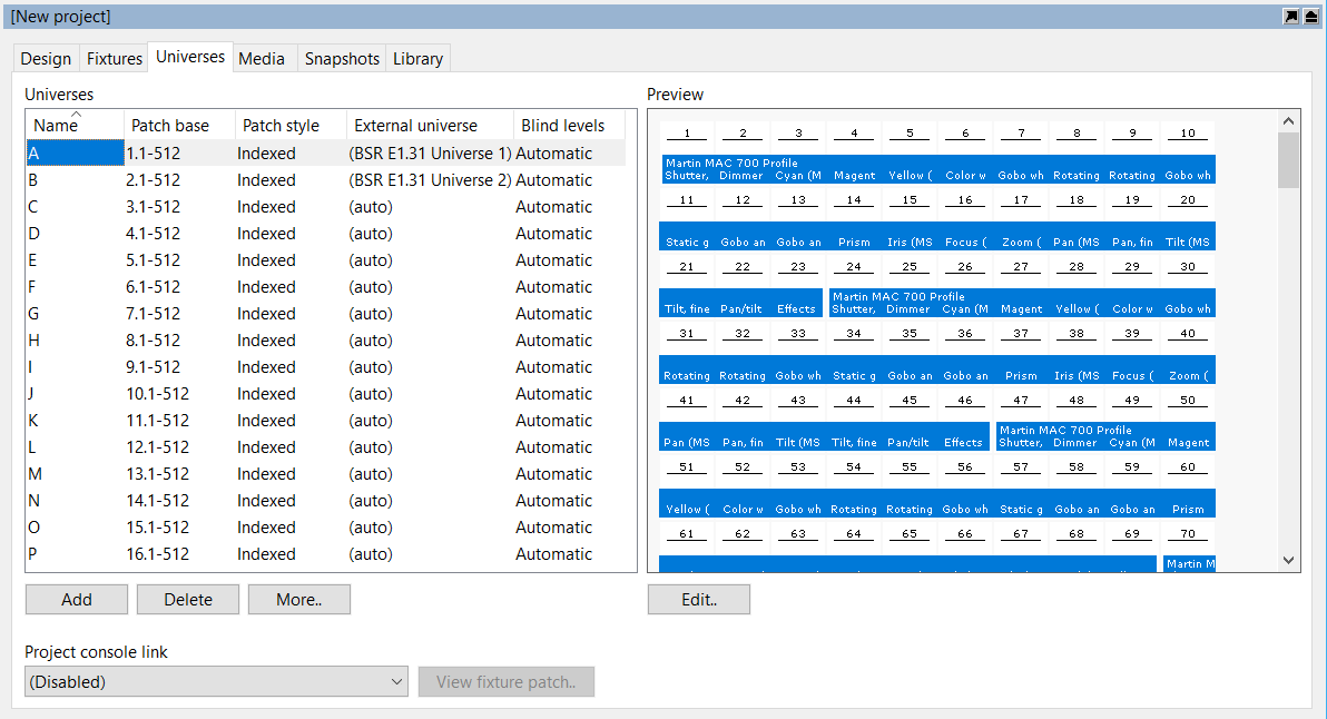
Universes are managed in the Universes tab of the Project window. The left hand side shows the universes of your project and the right hand offers a preview of the selected universe.
Capture automatically links external universes to internal universes, but also offers you the option of overriding the setup. To do this, double click on the External universe column property of a universe and choose the external universe you would rather use.
The Patch base property lets you choose the numerical location of a universe in relation to the other universes, independent of its name.
In a theatrical environment it may be more convenient to work with a contiguous range of channel numbers (for instance 1 – 2048). This can be achieved by setting the Patch style property to Contiguous.
5.3 Fixture Settings
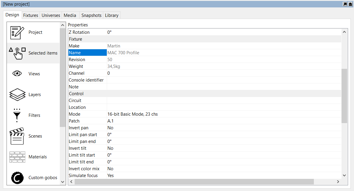
All fixture settings are available in the Design tab of the Project Window, as illustrated on the right hand side. The settings are divided in several categories. It is possible to select multiple fixtures at once to change a setting for all selected fixtures simultaneously.
5.4 Replacing Fixtures
To replace fixtures in your design, first select the fixtures you wish to replace, then activate the replace mode using the Replace command, locate the fixture type you wish to use instead in the Library tab and finally drag it onto one of the selected fixtures.
This way all the selected fixtures are replaced for the new fixture type chosen. You can also drop the new fixture type onto any other fixture or replaceable object not selected, but this way you can only replace on fixture or object at a time.
5.5 Adding Filters and Gobos
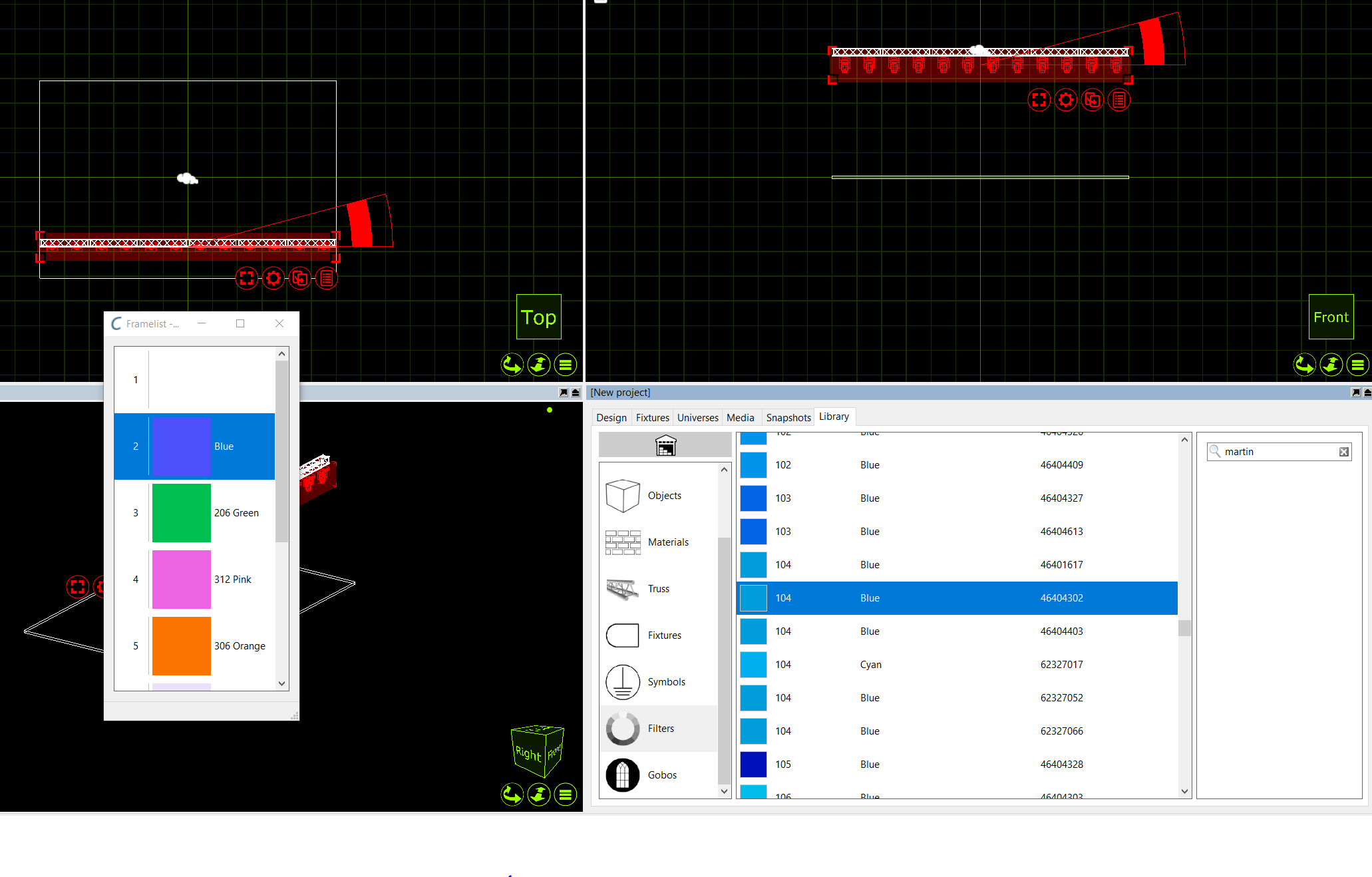
Filters and gobos can be added to fixtures using drag and drop from the Library tab where a selection of filters and gobos is available.
If you wish to apply the same filter or gobo to more than one fixture at a time then select the fixtures first and then drag and drop the filter or gobo onto any of the selected fixtures. This will insert one in each of the fixtures selected.
Gobos and filters can be removed from fixtures using the Remove filters and Remove gobos commands.
5.6 Custom Gobos
Custom gobos can be added in the Gobos category of the Design tab by clicking on the Add button. Once you have given the gobo a name you can choose an image for it. Use a square image, up to 256 by 256 pixels in size.
Finally drag and drop the gobo onto any fixture with a gobo slot to add it to the fixture. If you have selected multiple fixtures as you do this, the gobo will be added to all of them.
5.7 Customising Gobo and Color Wheels
Changing Gobo/Color frames in intelligent fixtures is very easy, simply open the current wheel via the fixture properties, double clicking on one of the current color/gobo slots in the properties opens the wheel, then drag a new color or gobo from the library to a slot on the wheel and the fixture is automatically updated.
5.8 The Fixtures Tab
The Fixtures Tab is part of the Project Window and shows all fixtures in the show and subset of their settings. The Fixtures Tab can be navigated and edited as a spreadsheet using the arrow and Enter/Return keys. Multiple row selection is also possible using the Shift and Ctrl/Cmd keys and useful when dragging and dropping fixtures from the Fixtures Tab.
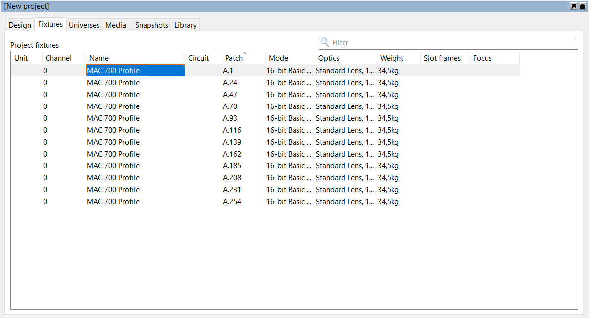
The Fixtures tab can be arranged in a number of ways. By default, the tab shows all fixtures currently in the project. It can be filtered by using the search function in the top right corner. It can also be filtered by clicking a column header to organize the data in ascending (or descending) order for that property. For example, in the image below, the window is filtered to show the source four fixtures ascending in patch data. The arrow in the Patch property column header denotes that the sheet is arranged showing patch data in ascending order. Clicking the Patch column header for a second time would toggle it into descending order.