8 Design Views
Capture has three design views, the Alpha, Beta and Gamma views. They all have the same capabilities and configuration options. Some of these are available from the view menu, some are available from the Views category of the Design tab.
8.1 Navigation
At the bottom right corner of each view is a cube that indicates the current camera location / orientation of the view. Each side of the cube is labelled to aid orientation.
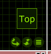
Below the cube sit three sit three buttons;
The rotation / panoration button. Hold the Shift key to toggle between rotation and panoration. The default behaviour can be changed in the Options. You can also hold the Ctrl key to rotate the camera without moving it.
The zoom buttons moves the camera closer to or further away from the current focus point. Hold the Shift key to move the focus point along with the camera.
The menu button displays the View menu.
8.2 Manipulation
Objects in a view can be selected by clicking on them. Use the Shift key to add objects to the selection and the Ctrl key to toggle individual object selection.
Click and drag a rectangle around multiple objects to select more than one object at once. If you drag from the left to the right, objects fully within the rectangle are selected. If you drag from the right to the left, objects fully or just partially within the rectangle are selected.
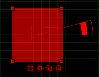
When one or more objects are selected, a red region outlines their extents.
Clicking and dragging anywhere inside the region moves the objects. Hold the Shift key to restrict the movement orthogonally.
While moving objects they may snap to the outlines of other objects. Hold the Escape key to disable snapping.
If multiple objects are selected, the corners of the outline region can be grabbed and moved. This causes the objects to be redistributed accordingly.
In addition to the rectangular red region, a red triangle may appear. This is a rotation tool. Click and drag its innermost segment to relocate it. Click and drag in one of the outermost segments to rotate the selected object(s) around the edge of the triangle. The inner region rotates the objects as a group while the outer region rotates the objects individually. Hold Shift to snap the rotation to steps of 5 degrees (configurable in the Options).
Below the sit four to five buttons. The first two buttons display a menu with all selection and modification commands from the Edit menu.
If the view is in Live mode, a middle button (with a power symbol inside it) appears. This can be used to open or close the Control pane.
The second last button (with an arrow inside) can be used to create a copy of the selected objects as well as drag the objects to other windows. For instance it could be used to drag fixtures into a DMX universe to patch them.
The last button (with a list inside) presents a popup window with details about the selected objects.
8.3 Control Pane
The control pane provides control of fixtures.
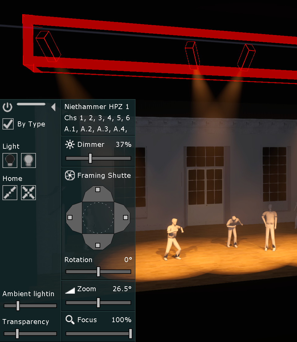
The leftmost pane is always present. Each selected type of fixture adds a control column to the right (unless the By Type option is unchecked, in which case each individual fixture adds a column).
At the top of the fixed pane are three controls; a power button that can be used to close the control pane, a resizing bar which be clicked and dragged to resize the control pane and finally an arrow button that hides and reveals the control columns.
Under the Light label are two buttons to quickly turn on and off the selected fixtures.
Under the Home label are two buttons to home the selected fixtures. The first button homes all parameters except pan and tilt, the second button homes all parameters.
The ambient lighting slider provides quick access to the view’s ambient lighting property.
The transparency slider controls the transparency of the control pane’s background.
8.3.1 Parameter Control
Most parameters are controlled using click and drag of sliders. Hold the Shift key to make fine adjustments.
Zoom, DMX mover and DMX rotator parameters can be edited by numeric entry on the keyboard by clicking on the current value. This way a specific field angle or fly bar height can be entered.
Pan and tilt parameters can be fanned by holdering the Ctrl key (on Windows) or Cmd key (on Mac). You can also hold the Alt key to apply an offset to rather than scale the fanning.
8.4 Polygon Editor
The polygon editor lets you edit the 2D polygon shape element of polygon forms. It is accessed by selecting a polygon shape and using the Model / Edit.. command from the Edit Menu.
The polygon editor automatically aligns the view’s camera to match the orientation of the polygon shape. Navigate the editor using the middle mouse button, scroll wheel / surface and corresponding buttons at the bottom right corner of the design view. Exit the polygon editor using the exit button at the bottom right corner.
To move points, click on them and drag them. To add points, hold the Ctrl key (on Windows) or the Cmd key (on Mac) and click on an edge. To remove a point, click on it to select it and then use the Delete command.
When hovering a point its X and Y coordinates are shown next to it. Input new coordinates using the keyboard and the Enter key, toggle between editing the X and Y coordinates using the Tab key.
When hovering an edge its length is shown next to it. Enter a new length using the keyboard and the Enter key. When hovering the centre of the edge both endpoints will be adjusted to the new length, when hovering closer to either of the ends of the edge only the endpoint on that side will be adjusted.