18 Object Properties
18.1 Location
The Location property is available on objects like fixtures, trusses, pipes or rigging points for example.
If you wish to add any location information, select the object, go the the Selected items category and and double click on the Location field under Geometry.
When you add location information to a truss or pipe, any fixture attached to it automatically inherits this property. The Location property of the fixtures will be shown with an arrow in front of it, a sign that this property is beeing pulled from the truss or pipe.
After you have added location information, you can identify or select those objects quicker in the following ways:
- Select all fixtures on a truss or pipe using the Select All - By Location command.
- On the Fixtures tab, use the Location column to sort fixtures by location, edit the location or use the search field to filter fixtures on a specific location.
- On Reports, add a Fixture Location Report, which automatically sorts fixtures by location.
18.2 Unique Properties
18.2.1 Angle
Angle measurements can be used both to measure angles as well as server as construction geometry for known angles.
Double click on the endpoints of an angle measurement to move and snap them to specific points.
In design views in Plot mode it is also possible to double click on the angle annotation and adjust its position (when plot adjustments are enabled).
The Angle property shows the current angle of the measurement. It serves both as an indication and a means of setting a specific angle.
The plot annotation Visible property makes it possible to hide the angle annotation on plots.
18.2.2 Cable
Cables can be used to add cable run information to plots and reports.
Double click on the endpoints of a cable to move them. When a single endpoint is selected, the Split command can be used to add extra points. Extra points can be removed using the Delete command.
The length of a cable run is calculated from its 3D distance plus any Cable extra added. It is then rounded up to the nearest multiple of the value specified by the Cable rounding property.
The Cable start and Cable end properties are shown at the end and start of the cable on plots.
In reports, cables are grouped by Cable type and Distance.
18.2.3 Casts Shadows
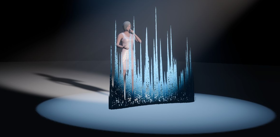
The Casts Shadows property refers to the ways a solid object can interact with light and is not to be confused with the transparency or opacity of a material. By default any object you add to a project has the Casts Shadows property to Yes. This means that when lit by a light source, the object will also cast a shadow.
In the picture below, observe the red cylinder. On the left, the property is set to Yes and the object is casting shadows. On the right, where the property on the red cylinder is set to No, the object does not cast a shadow anymore, whereas the beam is now unobstructibly lighting the orange cylinder.
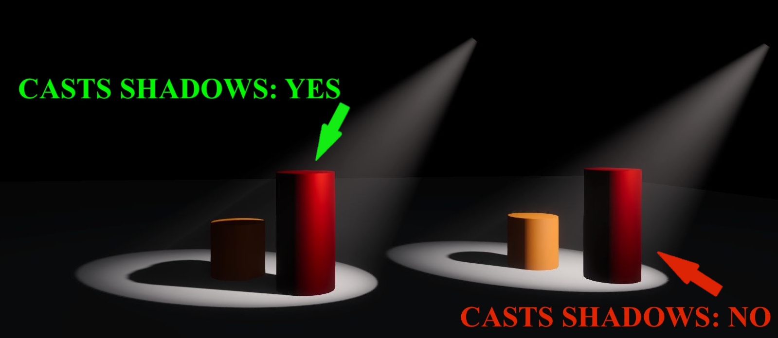
Changing the property to No on as many objects as possible is highly recommended for optimising performance on large projects.
As mentioned above, the Casts Shadows property of an object is not to be confused with the transparency/opacity of a material. A combination of the two however, could lead to some interesting results.
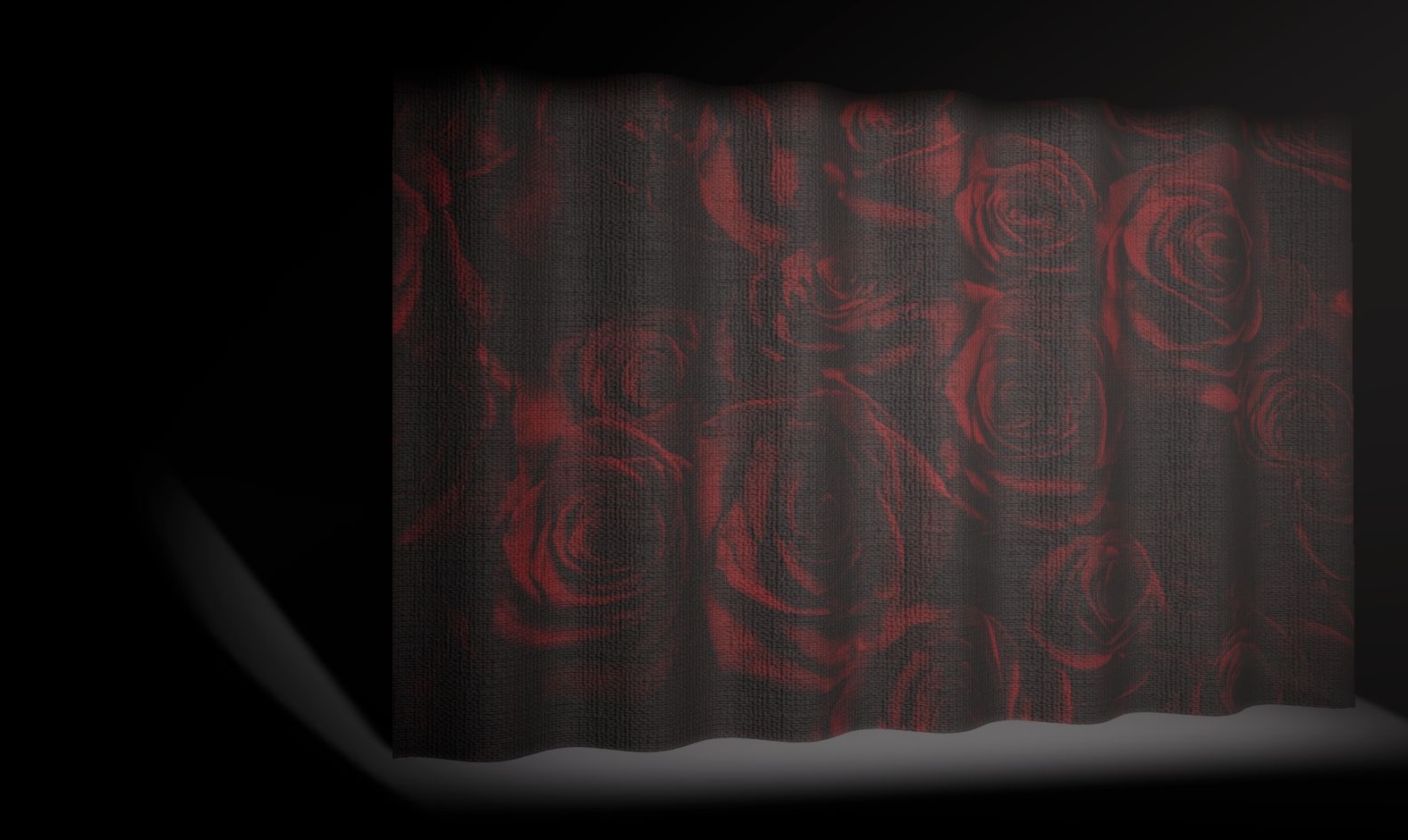
18.2.3.1 1st example - Semi transparent material
For this example we have placed an actor behind a gauze. We are using a curtain from our Library and the material applied to it has the following characteristics:
- Base Colour - Texture: a .jpg with roses.
- Transparency: 10%.
In the image below, the fabric may look as semi transparent, but the Casts Shadows property of the curtain is set to Yes. As a result, the light is not allowed to pass through the curtain.
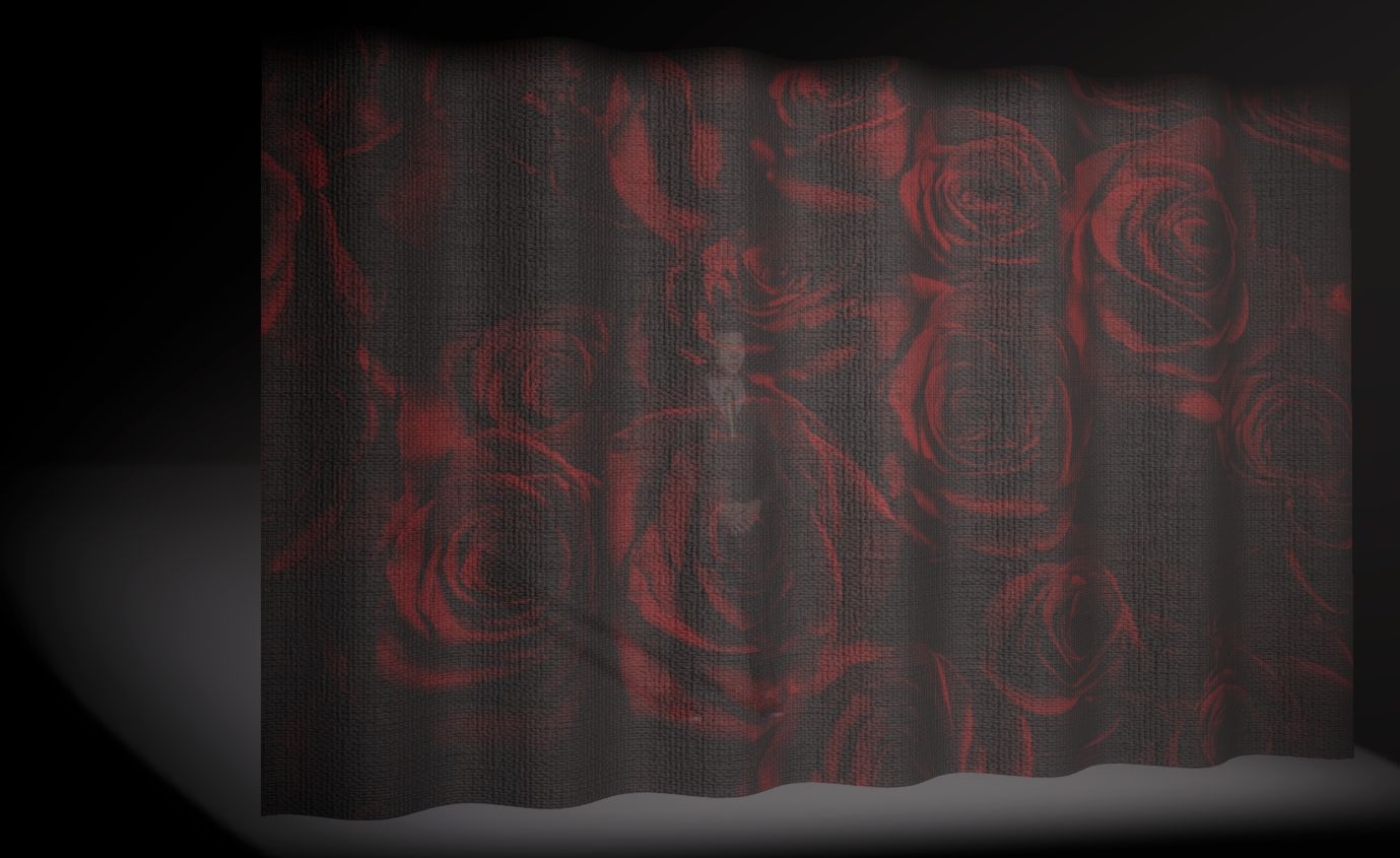
If we now disable shadows, some light is allowed to pass through, giving a much more realistic impression of a gauze. Different transparency percentage on the material will, of course, produce different results.
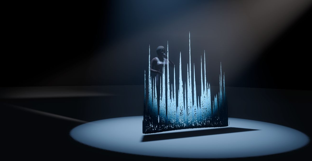
18.2.3.2 2nd example - Texture with Alpha channel
For this example we have placed an actor behind a wall. We are using a box from our Library and the material applied to it has the following characteristics:
- Base Colour - Texture: a .png with Alpha channel.
- Alpha mode: Mask.
- Alpha cutoff: 80%.
In the image below, the Alpha channel of the material allows you to see through. The Casts Shadows property of the box however is set to Yes, casting a shadow of the wall on the actor.
If we now disable shadows, the light is allowed to pass through, illuminating both the textured wall and the actor behind it.
18.2.4 Directional Snapper
Directional snappers are identical to Point Snappers, but also orient the snapping object so that it lines up with the other directional snapper.
Each library truss item in Capture contains an invisible directional snapper at each end of the truss with a Match property value of “Truss”. This means that you could build object groups with directional snappers inside that snap to library trusses.
There is also the option to add more Axial Steps that allow for more ways of axial alignment. In the case of triangular truss pieces for example, each end contains a directional snapper with 3 axial steps. This results in truss pieces snapping together in the correct way, even if the orientation of each piece was different.
18.2.5 Distance
Distance measurements can be used both to measure distances and serve as spacers or construction geometry by setting a specific distance.
Double click on the endpoints of a distance measurement to move and snap them to specific points.
In design views in Plot mode it is also possible to double click on the distance annotation and adjust its position (when plot adjustments are enabled).
The Distance property shows the current distance of the measurement. It serves both as an indication and as a way of setting a specific distance.
The plot annotation Visible property makes it possible to hide the distance annotation on plots.
The plot annotation Precision property controls how detailed the distance information is shown on plots.
18.2.6 DMX Mover
DMX Movers can move objects across a predefined range along the X Y Z axis.
Objects are associated with DMX Movers by setting their Motion fixture property. The names when making the selection come from the DMX Movers’ Unit property. It is also possible to drag and drop objects on DMX Movers - see the Manipulation section of Design Views for more details.
When a group is associated with a DMX Mover, all objects in that group will automatically behave as if they were too.
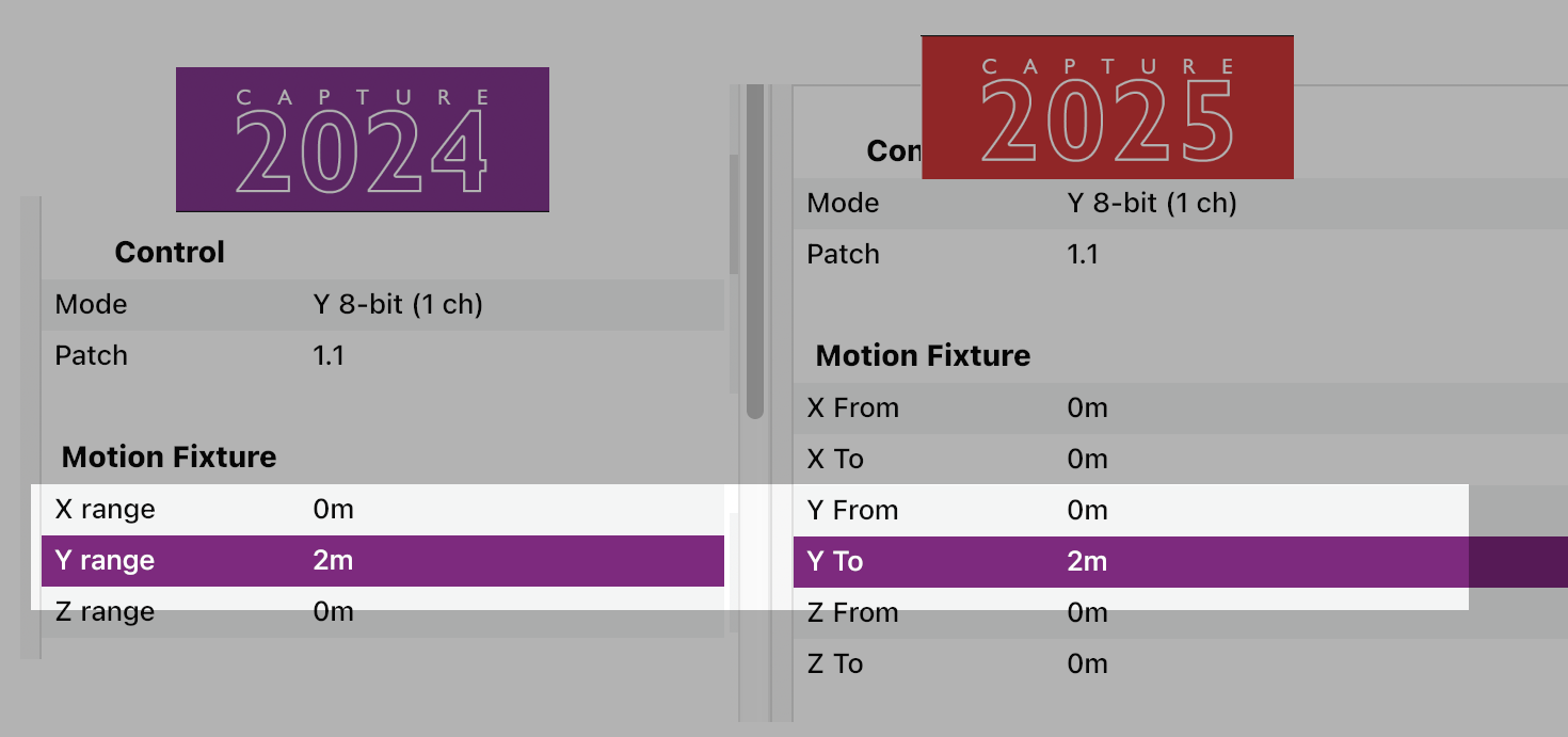
Movers can be configured to operate on only one axis, for example Y, so that the objects associated with it only move up and down. This is done by setting the X From/To and Z From/To properties of the DMX Mover to 0. You may also want to change the Mode of the DMX Mover to choose between 8-bit or 16-bit resolution and conserve DMX channels. See the DMX Movers section of the DMX Tables appendix for more information.
The From and To property defines the range, but it needs to contain the value 0. In the example below, the Lx bar is set at 5 meters, whereas the range of the mover is set from 2 to -2 meters. Setting the range from 1 meter to 3 for example, wouldn’t be possible, since the value does not pass 0.
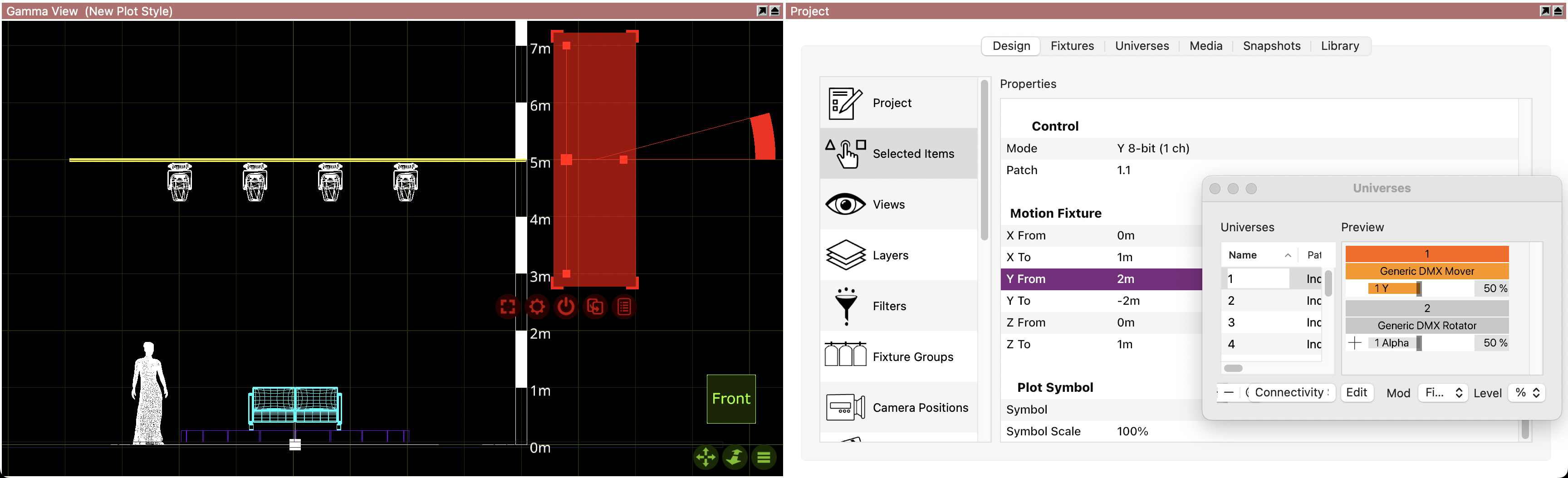
Opening a project that was created with a previous version, where only the Range property was available, the From value will be set to 0 and the To value will inherit the Range value.
LIMITATION: Although you can link DMX Movers and Rotators together to create more complex movements, you can’t have more than 20 units in the same chain.
18.2.7 DMX Rotator
DMX Rotators can be used to rotate objects around an axis and within a specific range.
Generally, the same principles as for DMX Movers apply.
Continuous rotation is available in the DMX modes that include a speed channel.
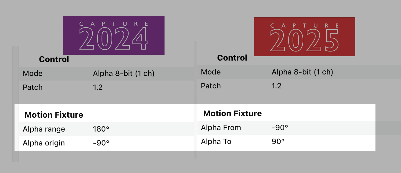
The Alpha From** and Alpha To property defines the range of the rotation of the object, but it needs to contain the value 0. In the example below, the revolving stage is set from -90º to 90º. Setting the range from 10º to 90º for example, wouldn’t be possible, since the value does not pass 0.
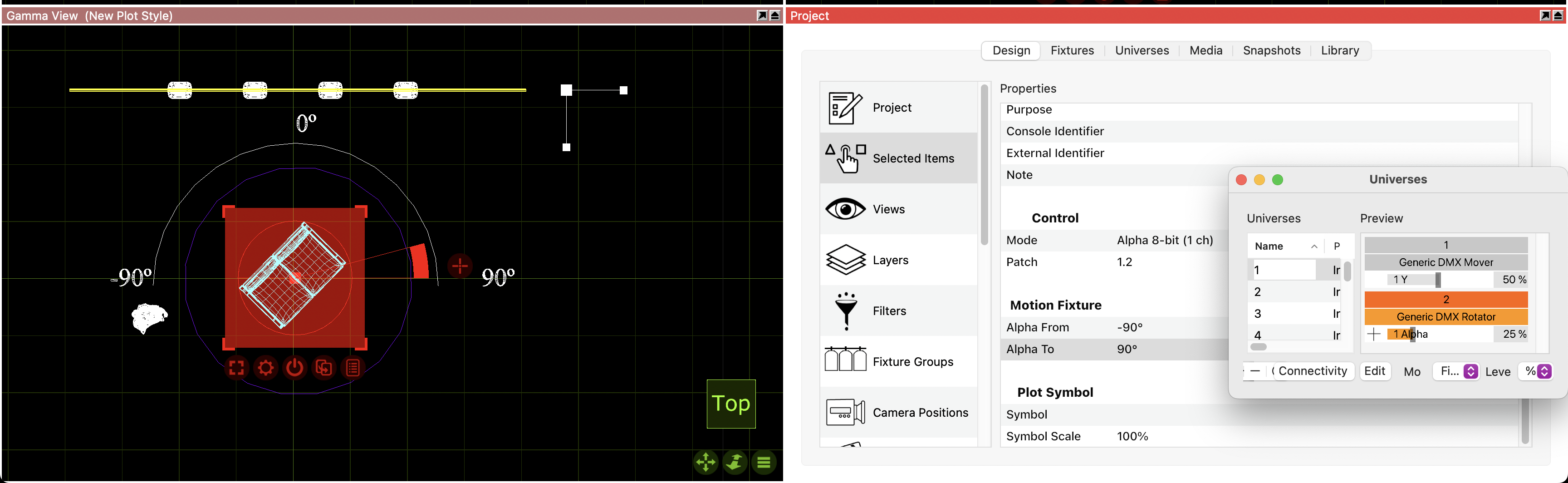
Opening a project that was created with a previous version, where the Range and Origin property were available, the Alpha From value will inherit the Origin and the Alpha To value will add the Origin to the Range. 180º + (-90º) = 90°
LIMITATION: Although you can link DMX Movers and Rotators together to create more complex movements, you can’t have more than 20 units in the same chain.
18.2.8 Fixture Plot Properties
Symbol will control which symbol is used on the plot for the selected fixture.
Symbol Usage will control which views the symbol actually appears in.
Direction snap is set to 30 degrees by default, this property controls the direction the fixture is facing on the plot.
Color by filter will set the fixture color to match the gel filter it has.
Focus is the property that allows text to be placed in front of the fixture to indicate where that fixture is focused. Ie, drums.
Show Optics is the property that controls whether or not the plot displays the optical information of the fixture.
Show Wattage is the property that controls whether or not the plot displays the wattage information of the fixture.
18.2.9 Focus Plane
Focus planes are widgets that provide visual guidance and illuminance information when focusing fixtures.
When selected, a focus plane is shown as a grid. When in Focus mode in a live view, all focus planes are shown by default and it is possible to choose between hiding them or showing them either as grids, solid white planes or as illuminance heatmaps.
The Width and Depth properties control the size of the focus plane.
The Grid width and Grid depth properties define the grid spacing of the focus plane.
The Heatmap min and Heatmap max properties define the illuminance levels in lux indicated by the focus plane when shown as a heatmap.
18.2.10 HDRI
HDRIs are widgets that allow loading HDR images for environmental lighting. An HDRI provides a backdrop to the environment and more interesting ambient and specular lighting.
HDR images loaded must be in the EXR format.
The location of an HDRI widget is irrelevant to the placement of the panoramic effect as it always follows the camera. The panoramic effect can be oriented using its Rotation property.
HDR images are not calibrated to a known level of illumination. The Intensity property controls the overall intensity of the HDRI. The Lighting Intensity property controls the intensity of the lighting from the HDRI, relative the Intensity property.
The Blur property controls the sharpness of the panoramic effect.
Only one HDRI widget can affect a view at the time. If multiple HDRI widgets are present, only one of them will be used.
18.2.11 Image
Images are good for creating reference underlays in designs. They are meant to be used in Wireframe and Plot mode in design views, and are invisible in Live mode in design views.
By default they show Capture’s application icon, but the image can be changed using the Image property.
Use the Width and Height properties to define the physical size of the image in your design.
Importing PDF or DWG files containing images using the Import Model commands will also produce Image objects in your design. It is in these cases that the Drawing unit property is used.
18.2.12 Line
Lines can be used to indicate many things, such as for instance the center line on stage.
Double click on the endpoints of a line to move them.
The Line style property allows for different choices of stroke style.
18.2.13 Line Snapper
The line snapper is a widget that Point Snappers and Directional Snappers snap to.
Each library truss item in Capture contains a line snapper along its main tubes with a Match property value of “Fixture”. As a result, setting the Match property to “Fixture” means that fixtures will snap to it.
18.2.14 Motion Construct
Motion constructs are used with tracking protocols. Each motion construct represents a trackable object. Associate the Motion Fixture property of objects with a motion construct to link them with the tracking data.
18.2.15 Point Snapper
Point snappers are widgets that make it possible to create object groups that snap in custom ways. Two point snappers snap to eachother like magnets, without altering the orientation of the snapping object.
The Match property works like a filtering mechanism - only snappers with the same Match property value will snap to each other.
18.2.16 Reflection Plane
Reflection planes are widgets that assist the rendering engine in the creation of secondary reflections.
When placed and carefully aligned with flat surfaces to which materials with high smoothness have been assigned, a mirror-like effect can be achieved.
The Width and Depth properties control the size of a reflection plane.
18.2.17 Report Item
Report items are widgets that make it possible to add equipment and information to reports.
The Section property decides whether the report item’s information sorts under Other or Trusses. When Other is chosen, the Other type can be used to add more specific information about what type of equipment is specified.
The Name property can be used to identify what specific type of truss or Other type is specified.
The Multiplier property specifies how many items are specified.
The Rating and Weight properties specify the rating and weight of one item.
You can group the Report item with an object or a symbol. The icon will disappear, but it can become visible again in a specific view, if you enable hidden objects on that view.
18.2.18 Ruler
Rulers are good for aiding the reader of a plot judge the size of objects and distance between them.
Double click on the endpoints of a ruler to move them.
The Segment length property defines the sample point intervals.
The Alignment property defines the location of the 0 point.
18.2.19 Smoke Box Properties
Control the overall amount of smoke in a smoke box using the Density property. You can also adjust the Variation from perfect haze to puffy clouds. Edge softness adds a soft edge to smoke boxes.
Smoke boxes are animated in real-time and the speed of the animation is controlled through the Speed property. This property is shared by all smoke boxes.
Smoke can also be patched to DMX. A smoke box can be patched by drag and dropping it in a DMX universe view like any fixture, or by assigning an address to the Patch property in the Design tab. See Appendix A for details on the DMX channel layout.